Technical Data
Ø DIMENSIONS TOLERANCE
l Tolerances for thickness, width and lateral curvature are presented on Table 3, Table 4 and Table 5, respectively.
Table 3
Table 4
Table 5
l Length
The tolerance for length shall be from -0% to +2%, considering the total indicated on Purchase Order.
l Burr
For the thickness < 0.8mm=> Burr< 0.01mm
For the thickness >0.8mm => Burr < 0.02mm
Ø DIMENSIONS AND PRODUCTS WEIGHT
l Coil core ( Interal dimensions from bobbin)
signi transformer aluminium strip thickness T≤0.15mm, the internal dimension from bobbin shall be ∮I=76.2mm(3”). The material from internal bobbin shall be by aluminum with thickness such that it resists the efforts of the coil and prevent deformations during transport and handling.
signi transformer aluminium strip thickness 0.15<T<2.5mm, the internal dimension from bobbin shall be ∮I=390mm. The material from internal bobbin shall be by press paper with thickness such that it resists the efforts of the coil and prevents deformations during transport and handling.
The width of the internal bobbin shall be the same as the aluminum foil.
l Coil of signi transformer aluminium strip
The external diameter from coil of aluminum foil shall not exceed 650mm.
The weight from coil of aluminum foil shall not exceed the total gross weight of 650kg.
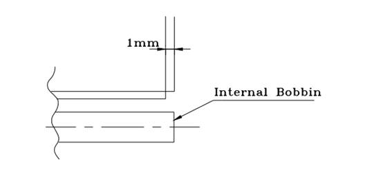
l Symmetry of the signi transformer aluminium strip
During the winding of the signi transformer aluminium strip (lamination). Shall be maintained the symmetry by the layers, keeping the perfectly lateral face milling.
The maximum tolerance acceptable for face milling alignment shall be 1mm, as presented on Figure below.
l Tolerances for thickness, width and lateral curvature are presented on Table 3, Table 4 and Table 5, respectively.
Table 3
| Thickness (mm) | Tolerance (mm) |
|---|---|
| Up to 0.19 | ±0.01 |
| 0.20 ≤ T ≤0.50 | ±0.02 |
| 0.51≤ T ≤ 1.00 | ±0.03 |
| 1.01≤ T ≤ 1.50 | ±0.04 |
| 1.51 ≤ T ≤ 2.00 | ±0.05 |
| 2.01 ≤ T ≤ 2.50 | ±0.06 |
Table 4
| Width(mm) | Tolerance (mm) |
|---|---|
| <200 | ﹢0.3/-0 |
| 201≤W≤400 | +0.4/ -0 |
| 401≤W≤600 | +0.6/-0 |
| 601≤W≤1000 | +1.5/-0 |
| >1000 | +2.0/-0 |
Table 5
| Width (mm) |
Lateral Curvature Measured on 2000/1000mm Strip length |
|
| Over | Up to and Including | |
| 15 | 100 | 6mm /1.5mm |
| 100 | 300 | 4mm /1.5mm |
| 300 | 600 | 3mm /0.7mm |
| 600 | 1540 | 2mm / 0.5mm |
The tolerance for length shall be from -0% to +2%, considering the total indicated on Purchase Order.
l Burr
For the thickness < 0.8mm=> Burr< 0.01mm
For the thickness >0.8mm => Burr < 0.02mm
Ø DIMENSIONS AND PRODUCTS WEIGHT
l Coil core ( Interal dimensions from bobbin)
signi transformer aluminium strip thickness T≤0.15mm, the internal dimension from bobbin shall be ∮I=76.2mm(3”). The material from internal bobbin shall be by aluminum with thickness such that it resists the efforts of the coil and prevent deformations during transport and handling.
signi transformer aluminium strip thickness 0.15<T<2.5mm, the internal dimension from bobbin shall be ∮I=390mm. The material from internal bobbin shall be by press paper with thickness such that it resists the efforts of the coil and prevents deformations during transport and handling.
The width of the internal bobbin shall be the same as the aluminum foil.
l Coil of signi transformer aluminium strip
The external diameter from coil of aluminum foil shall not exceed 650mm.
The weight from coil of aluminum foil shall not exceed the total gross weight of 650kg.
l Symmetry of the signi transformer aluminium strip
During the winding of the signi transformer aluminium strip (lamination). Shall be maintained the symmetry by the layers, keeping the perfectly lateral face milling.
The maximum tolerance acceptable for face milling alignment shall be 1mm, as presented on Figure below.
RELATED READ: